The rocker switch, or as it is also called the marching, double, reverse, cross, is an element of the power supply network that inverts (translates into the opposite state) switching of the conductors connected to it.
A rocker switch is used to control a group or one lighting fixture from several places.
In this material we will talk in detail about the principles and features of the operation of such switches, as well as provide the most common ways to connect them.
Scope of application of cross over devices
Rocker switches are not used often, but their role in organizing lighting cannot be underestimated. Imagine a situation when only one switch is installed in a long corridor or at the beginning of a flight of stairs and you have to travel considerable distances in the dark to turn on the light.
The installation of a two-way switch through passage is quite capable of solving this problem, and the cross over (cross) will become indispensable:
- in a three-level apartment - install near the site of the second floor;
- in a large corridor or hall - installed near each door, it will greatly facilitate movement in the dark;
- in the bedroom - you can install one near the door and two near the resting place, and no longer have to get up to turn off the light.
You can also use the rocker switch to turn on lighting on the street or in the garage, controlling the lamp from the house, gazebo, terrace, etc.

When leaving the room at night in the corridor, the user can turn on the light immediately, and not move in a dark room in search of a switch
Varieties of cross over switches and their marking
The choice of cross over switches has to be made, based on a modest list of distinctive characteristics. They are produced by many well-known companies, including such as Legrand, ABB, Schneider.

Lever electrical equipment is considered more reliable and therefore it is often used in factories, in public places
Rocker switches classify:
- By the method of inclusion, they are divided into rotary, keyboard and lever types;
- By the method of installation - on devices for internal and external installation.
You cannot find two-gang cross-over switches of the cross type as such on sale. But you can take advantage of the Ultra Series device from the renowned electrical equipment supplier Schneider Electric by taking two single-gang, cross-type, modular-type cross-units and installing them in one enclosure. If these models are not available, mount two single-key switches next to each other.

To control two or three groups of lighting devices, two or three-key passage switches are used, and cross, in most cases, are set separately for each group of lamps
When choosing any electrical device, it is necessary to focus on its class of protection against external factors - IP.
In most cases, in devices of this type, IP is quite high and exceeds a value of 40, which allows the possibility of use in rooms with traditional high humidity, as well as its location on the street under a visor.

In rotary toggle switches, the contacts are closed using a special rotary mechanism. They cost a little more than keyboards, but are considered more reliable.
In order to properly connect the electrical equipment, it is important to understand the designations and diagrams printed by the manufacturer on the back.

So in the diagram the cross-type switch is indicated. The same scheme is applied to the device, arrows indicate the location of the input and output contacts
If in a conventional switch the marking with the letter L is used to indicate an incoming phase terminal, and L1, L2, L3 for outgoing, then in the case of a paired switch, the numbers 1, 2, 3, 4 can be used, and the incoming and outgoing terminals are indicated by arrows.

On the front side of the circuit breaker, manufacturers also sometimes mark - for a walk-through, these are two arrows in the form of a triangle, for a cross over - a grid
Next, we will consider the installation features and options for possible connection schemes using the example of a household cross-type circuit breaker complete with transition switches.
The principle of operation and features of rocker switches
To understand the principle of operation of the cross over switch, it is necessary to study the control scheme of lighting points of 3-5 points.
But since the cross-over switch is always installed between the walk-through and never used on its own, you first need to understand how the lighting activation and shutdown circuit works with conventional and walk-through switches.

The control circuits of lighting devices from three points differ from the scheme in two directions only by the presence of a cross switch
So, the functions of a conventional switch include opening and closing a circuit - when you press the upper half of the key, the light turns on, the bottom turns off. But the state of lighting in a circuit with two loop-through devices is completely independent of the position of the keys of one of them.
Pressing a key only switches the connection from one circuit to another. In order for the circuit to close, it is necessary that both devices close contact with one of the conductors laid between them.

The passage switch is also called a two-way switch. The diagram clearly demonstrates that the user, using any of them, will be able to turn the light on and off
The mechanism of different types of devices differs in the number of terminals:
- in the usual two of them;
- there are three in the transition;
- in the cross - four terminals.
The more complex the device, the more it requires better workmanship. Therefore, the design of the rocker switches, which have a large number of terminals, is distinguished by high strength, wear resistance, and corrosion resistance.
Most models have a high level of protection (IP) from negative external factors - dust, moisture.

If the through switches are always used only in pairs, the number of flip switches can be any - at least one, at least ten
Like walk-through, cross-over switches switch connections from one conductor to another. But their difference lies in the fact that there are already two input contacts, not one, and their switching also needs to be controlled. The principle of operation of the device is based on pair contact switching.
Connectivity options
Just as the loop-through switches cannot be used separately, but are connected only in pairs, the rocker switches are used with only two loop-throughs. In this case, up to 10 pieces of cross switches can be used, and they will always be between the walk-throughs.

In the diagram, the phase conductor is indicated in red, and the neutral conductor is blue. And 1 - the basic connection diagram; And 2 is another version of the connection diagram; B1 is a wiring method in which each element of the circuit is connected through a junction box; В 2 - connection method using an old small junction box and a socket out of a dismantled conventional switch
There may be many options for the circuits used for connection: installation is carried out through the junction box or past it, several lighting groups are connected.
Improve the system by installing centralized management.

The cross-over switch type is always designed for one lighting group. If it is necessary to connect two groups of luminaires, either two switches are used or make up one of two separate units
Installation through a junction box
This is a traditional way of connecting, which has both disadvantages and advantages. The pluses include the ability to quickly detect damaged sections of wires in case of problems in the circuit.
In addition, this method involves the traditional laying of wires, which helps during subsequent repair or installation work to determine where the wires are laid, and to preserve the integrity of the power grid.

Connection diagram of passage and cross switches in the lighting control system from several places. L is the phase conductor; N is zero
When wiring from the junction box to the walk-through switches, three-wire wires are laid. A two-wire wire leads from the cross switch to the walk-through.
The sequence of actions when connecting a circuit in which wires pass through a junction box is as follows:
- A two-wire phase wire from the electrical panel is brought into the box. The neutral conductor of the power cable is immediately connected to the neutral conductor of the luminaire, and the phase conductor is connected to the common conductor of the first pass-through switch No. 1, to input terminal 1 (see figure above).
- To the output terminals 3 and 4, the other two conductors of the three-wire wire are connected, which in the junction box will be connected to the two conductors of the No. 2 changeover switch.
- Set the middle rocker switch. The correct connection of the cross-switch conductors is indicated on the diagram drawn on the device itself.
The second pass-through switch is connected in the same way as the first, but the common conductor is led out through the junction box to the lamp.

The power grid for organizing lighting using junction boxes is good in that in case of a malfunction it is easier to identify a damaged section of the wire
If the connection in the junction box was carried out by the method of twisting, all exposed areas are carefully insulated to prevent short circuits.
This is done using insulating tape or heat-shrink tubing, which can serve as a marking for conductors.
We also recommend reading our other material, where we spoke in detail about the installation of the soldering box. Read more - read on.

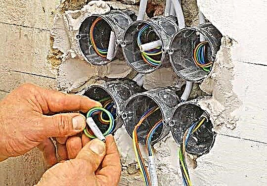
Professional connection is immediately visible - all wires are laid in a junction box compactly and neatly
Direct connection method
Compounds are a weak link in any electrical network - this is where oxidation occurs. Regardless of whether these are side clamps or spring-loaded terminal blocks, they burn out first, the wire itself remains intact, since the machine protects it from burnout.
To minimize the number of connections, connect without a junction box.

They also come to this connection method because users do not always want to see several junction boxes on their wall - these are additional elements that you have to hide from your eyes
How is the installation of the electrical system without a junction box:
- A cable with two conductors is pulled from the electrical panel - phase, zero. The latter lead directly to the lamp.
- The phase is connected to the input terminal of the passage switch. From two output terminals, two phase wires lead to the cross.
- Two phase conductors are laid from the output contacts of the reversing switch and connected to the second passage.
- The common conductor from the second pass-through switching device leads to the lamp and closes the power supply.
All wires must be marked during electrical work. Otherwise, next time, when carrying out electrical installation works, it will be difficult to identify their nature.

All the conductors that are interconnected in the socket, it will be difficult enough to fit there. Therefore, they use flatter and more compact terminals. You can also solve the placement problem by using large sockets - with a depth of 60 mm
There are other ways to hide junction boxes. For example, by mounting the box behind a stretch ceiling.
This option cannot be called a win-win, since in complex cases of breakdowns, the detection of a malfunction may not be limited to one box, and then you will have to remove the ceilings in more than one room.

Distribution boxes are also installed behind a suspended ceiling. In this case, all of them are concentrated in one place, and access is provided by a revision hatch device
Check the connection as follows: each time you press the key of any switch, including cross, the state of the lighting should change - the light turns off and on. Problems can arise if errors are made during the connection - the circuit is incorrectly assembled, the contacts are reversed.
The reason for the malfunctioning of the toggle switch can be eliminated only by carefully checking the connection directly at the installation site.
Typical connection errors
Ignoring the markings and circuits printed on the switches, lead to errors in connection, to the malfunction of the circuit. The most common problem that occurs, especially when installing walk-through switches, is that the user incorrectly determines the location of the incoming contact.
On different devices, it can be located in different ways, so the label must be read. All the intricacies of the choice of passage switches are discussed in this material.

If it was not possible to determine the exact location of the incoming terminal, then the device is called with a multimeter or indicator screwdriver
When connecting the cross over cross switches, problems arise if the pair wires from the loop-through devices are connected to terminals located on the wrong side.
Most often, the device involves cross-connection.

Before connecting, always check the circuit. The input and output contacts of the rocker switch can be located in different ways.
TN-S Cross-Lighting
Connecting a cross switch in the TN-S mains, which is characterized by the separation of the working (N) and protective (PE) zero, has some nuances. Unlike the old, not-so-safe TN-C system, the electrical network carried out according to the new standards uses 3 cores for a single-phase voltage supply, and 5 for three-phase ones.
The wire, which performs the function of zero (N, marked in blue), leaves the electrical panel, passes through the junction box and connects to the zero of the lamp. The ground wire (PE, marked yellow-green) is connected to the ground wire of the lighting fixture.

The installation of electrical networks through the TN-S system significantly increases the cost of materials, but reduces the risks associated with the operation of electrical equipment
How to establish centralized lighting control?
A control network from several places has a significant drawback - all the switches involved in it do not have a fixed position. Therefore, it is impossible to determine whether the light in the room is on or off if there is no electricity. Installing a conventional switch in front of the first loop-through eliminates this problem.
One more element is added to the already known connection scheme of cross over and pass-through switches - the usual one-key switch.Place it in the same room or take it to the front door. In the on state, it will allow the system to work in normal mode. In the off state, the circuit will be completely de-energized and the light will not light regardless of the position of the switches.
Centralized control can even be improved with a pulse relay. It has great functionality and allows you to control a separate group of electrical equipment or lighting throughout the house.
Operating principle of the cross over switch:
How does the rocker switch work:
Electrical connection TN-S (with ground, PE):
Mounting a rocker switch is not as difficult as it seems at first glance. To simplify the understanding of the principle and patterns of connection, you can understand the operation of a conventional single-key device, go on to study the operation of the transition switch, and then the circuit diagram of the control using the cross switch will seem quite simple. The main thing, with self-assembly, is to comply with safety requirements.
If you have experience installing the rocker switch yourself, please share it with our readers. Tell us what points you should definitely pay attention to. Leave your comments, ask questions in the block under the article.