Making homemade voltage stabilizers is a fairly common practice. However, for the most part, stabilizing electronic circuits are created that are designed for relatively small output voltages (5-36 volts) and relatively low power. Devices are used as part of household equipment, nothing more.
We will tell you how to make a powerful voltage regulator with your own hands. In our proposed article, we describe the manufacturing process of a device for working with a network voltage of 220 volts. Based on our tips, you can easily cope with the assembly yourself.
Voltage stabilization of a household network
The desire to provide a stabilized voltage of the household network is an obvious phenomenon. This approach ensures the safety of operating equipment, often expensive, constantly necessary in the household. And in general, the stabilization factor is the key to increased safety of the operation of electric networks.
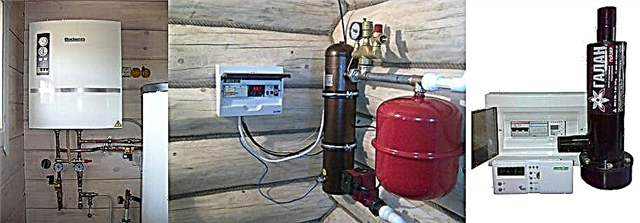
For domestic purposes, they most often purchase a stabilizer for a gas boiler, the automation of which requires a power supply, for a refrigerator, pumping equipment, split systems and similar consumers.

Industrial design of a voltage stabilizer, which is easy to purchase on the market. The range of such equipment is huge, but there is always the opportunity to make your own design
There are many ways to solve this problem, the simplest of which is to buy a powerful voltage regulator manufactured in an industrial way.
There are a lot of offers of voltage stabilizers in the commercial market. However, acquisition opportunities are often limited by the cost of devices or other points. Accordingly, an alternative to buying is the assembly of a voltage stabilizer with your own hands from available electronic components.
Provided that you have the appropriate skills and knowledge of electrical installation, the theory of electrical engineering (electronics), wiring circuits and soldering elements, a home-made voltage stabilizer can be implemented and successfully applied in practice. There are such examples.

Something like this might look like stabilization equipment made by yourself from affordable and affordable radio components. Chassis and housing can be selected from old industrial equipment (for example, from an oscilloscope)
220V power supply circuit stabilization solutions
Considering possible circuit solutions for voltage stabilization taking into account relatively high power (at least 1-2 kW), one should keep in mind the variety of technologies.
There are several circuit solutions that determine the technological capabilities of devices:
- ferroresonance;
- servo-driven;
- electronic;
- invertor.
Which option to choose depends on your preference, available materials for assembly and skills in working with electrical equipment.
Option # 1 - Ferroresonance Scheme
For self-production, the simplest version of the circuit is the first item on the list - the ferroresonant circuit. It works by using the effect of magnetic resonance.

The structural diagram of a simple stabilizer made on the basis of chokes: 1 - the first choke element; 2 - the second throttle element; 3 - capacitor; 4 - input voltage side; 5 - output voltage side
The construction of a sufficiently powerful ferroresonant stabilizer can be assembled on only three elements:
- Throttle 1.
- Throttle 2.
- Capacitor.
However, simplicity in this embodiment is accompanied by a lot of inconvenience. The design of a powerful stabilizer, assembled according to a ferroresonant circuit, turns out to be massive, bulky, and heavy.
Option # 2 - autotransformer or servo drive
In fact, this is a scheme where the principle of an autotransformer is used. The voltage transformation is automatically carried out by controlling the rheostat, the slider of which moves the servo drive.
In turn, the servo drive is controlled by a signal received, for example, from a voltage level sensor.

A schematic diagram of a servo-drive unit, the assembly of which will allow you to create a powerful voltage stabilizer for home or cottage. However, this option is considered technologically obsolete.
Approximately in the same way a relay-type device operates with the only difference being that the transformation coefficient changes, if necessary, by connecting or disconnecting the corresponding windings using a relay.
Schemes of this kind already look more technically complicated, but at the same time they do not provide sufficient linearity for voltage changes. Manually assemble the relay device or on a servo drive is permissible. However, it is wiser to choose an electronic option. The cost of effort and money is almost the same.
Option # 3 - electronic circuit
Assembling a powerful stabilizer according to the electronic control scheme with an extensive assortment of radio components for sale becomes quite possible. As a rule, such circuits are assembled on electronic components - triacs (thyristors, transistors).
A number of voltage stabilizer circuits have also been developed, where power field-effect transistors are used as keys.

Block diagram of the electronic stabilization module: 1 - input terminals of the device; 2 - triac transistor winding control unit; 3 - microprocessor unit; 4 - output terminals for load connection
It is quite difficult to make a powerful device completely electronically controlled by a non-specialist, it’s better to buy a ready-made device. In this matter, experience and knowledge in the field of electrical engineering is indispensable.
Under independent production, it is advisable to consider this option if there is a strong desire to build a stabilizer, plus the accumulated experience of an electronics engineer. Further in the article, we will consider a design of electronic design suitable for DIY manufacturing.
Detailed assembly instructions
Considered as an independent manufacture, the circuit is rather a hybrid option, since it involves the use of a power transformer in conjunction with electronics. The transformer in this case is used from among those that were installed in TVs of old models.

Here's an approximately power transformer required for the manufacture of a makeshift stabilizer design. However, it is not ruled out the selection of other options or do-it-yourself winding
True, in TV receivers, as a rule, TS-180 transformers were installed, while a stabilizer requires at least TS-320 to provide an output load of up to 2 kW.
Step # 1 - making the stabilizer body
Any suitable box based on an insulating material such as plastic, textolite, etc. The main criterion is the sufficiency of space for the placement of a power transformer, an electronic board and other components.
Also, the housing can be made of fiberglass sheet by fastening individual sheets using corners or in another way.

It is permissible to choose a housing from any electronics that is suitable for placing all the working components of a homemade stabilizer circuit. You can also assemble the case yourself, for example, from sheets of fiberglass
The stabilizer box must be equipped with slots for installing the switch, input and output interfaces, as well as other accessories provided by the circuit as control or switching elements.
Under the manufactured case, you need a base plate, on which the electronic board will “lie” and the transformer will be fixed. The plate can be made of aluminum, but insulators should be provided for mounting the electronic board.
Step # 2 - making a circuit board
Here, you will need to initially design a layout for the placement and bundle of all electronic parts according to the circuit diagram, except for the transformer. Then, a sheet of foiled textolite is marked on the layout and the created trace is drawn (printed) on the side of the foil.
Next, the board is etched using the appropriate solution (for electronic engineers, the method of etching the boards should be familiar).

You can make a stabilizer circuit board in quite affordable ways directly at home. To do this, you need to prepare a stencil and a set of tools for etching on foil textolite
The printed copy of the wiring obtained in this way is cleaned, tin-coated, and all radio components of the circuit are assembled, followed by soldering. This is how the electronic circuit board of a powerful voltage regulator is manufactured.
In principle, you can use third-party services for etching printed circuit boards. This service is quite affordable, and the manufacturing quality of the “signet” is significantly higher than in the home version.
Step # 3 - voltage stabilizer assembly
A board equipped with radio components is prepared for external wiring. In particular, external communication lines (conductors) with other elements, such as a transformer, switch, interfaces, etc., are output from the board.
A transformer is installed on the base plate of the case, the circuit of the electronic board is connected to the transformer, the board is fixed on the insulators.

An example of a home-made voltage stabilizer of a relay type, manufactured in a home environment, placed in a housing from a worn-out industrial measuring device
It remains only to connect external elements mounted on the housing to the circuit, install the key transistor on the radiator, after which the assembled electronic structure is closed by the housing. The voltage regulator is ready. You can begin to configure with further tests.
The principle of operation and homemade test
The regulating element of the electronic stabilization circuit is a powerful field effect transistor type IRF840. The voltage for processing (220-250V) passes through the primary winding of the power transformer, is rectified by the VD1 diode bridge, and enters the drain of the IRF840 transistor. The source of the same component is connected to the negative potential of the diode bridge.

Schematic diagram of a high power stabilizing block (up to 2 kW), on the basis of which several devices were assembled and successfully used. The scheme showed the optimal level of stabilization at the indicated load, but not higher
The part of the circuit, which includes one of the two secondary windings of the transformer, is formed by a diode rectifier (VD2), a potentiometer (R5), and other elements of the electronic controller. This part of the circuit generates a control signal, which is fed to the gate of the IRF840 field effect transistor.
In the event of an increase in the supply voltage, the control signal decreases the gate voltage of the field-effect transistor, which leads to the closure of the key. Accordingly, at the load connection contacts (XT3, XT4), a possible increase in voltage is limited. The reverse option is a circuit in case of a decrease in the mains voltage.
Setting up the device is not particularly difficult. Here you will need a conventional incandescent lamp (200-250 W), which should be connected to the output terminals of the device (X3, X4). Further, by rotating the potentiometer (R5), the voltage at the marked terminals is brought to the level of 220-225 volts.
Turn off the stabilizer, turn off the incandescent lamp and turn on the device already with a full load (not higher than 2 kW).
After 15-20 minutes of operation, the device is turned off again and the temperature of the radiator of the key transistor (IRF840) is monitored. If the heating of the radiator is significant (more than 75º), you should choose a more powerful heat sink.
If the process of manufacturing the stabilizer seemed too complicated and irrational from a practical point of view, without any problems you can find and purchase a factory-made device. The rules and criteria for choosing a stabilizer for 220 V are given in our recommended article.
The video below discusses one of the possible homemade stabilizer designs.
In principle, you can take note of this version of the improvised stabilization apparatus:
Assembling a block that stabilizes the mains voltage with your own hands is possible. This is confirmed by numerous examples when radio amateurs with little experience quite successfully develop (or use the existing one), prepare and assemble an electronics circuit.
Difficulties with the purchase of parts for the manufacture of a stabilizer-homemade is usually not noted. The cost of production is low and naturally pays off when the stabilizer is put into operation.
Please leave comments, ask questions, publish photos on the topic of the article in the block below. Tell us about how to assemble a voltage regulator with your own hands. Share useful information that may come in handy for beginners visiting electrical engineering.